

Products
Multi-layer deposition system for manufacture
AFTEX-6000series
Solid-source ECR plasma deposition system that makes it possible to form multi-layer films from a large number of materials.
- Low temperature process
- High refractive index control
- High-speed reactive film formation
- Multilayer film
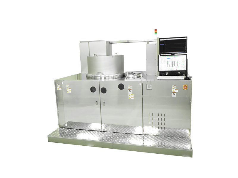
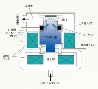
A solid-source electron cyclotron resonance (ECR) plasma deposition system forms high-quality thin films by directly reacting a low-pressure, high-density ECR plasma flow with particles sputtered from a solid source (target) placed at the outlet of the plasma flow. AFTEX-6200 is equipped with two ECR plasma sources and enables automatic transfer and deposition, which is optimal for multilayer film deposition.
- Deposition Characteristics
- Product Features
- Standard Specification
- Principles and Features of ECR Plasma Deposition
Membranes and multi-layer films of wide range of materials
Any solid material that can be fabricated into a sputtering target can be used as the raw material, so films of various oxides and nitrides can be formed, as well as multi-layer films, by combining them with introduced gases such as oxygen or nitrogen. For example, if Si is used as the solid source, it is possible to form single-layer and multi-layer films of SiO2, Si3N4, and Si.
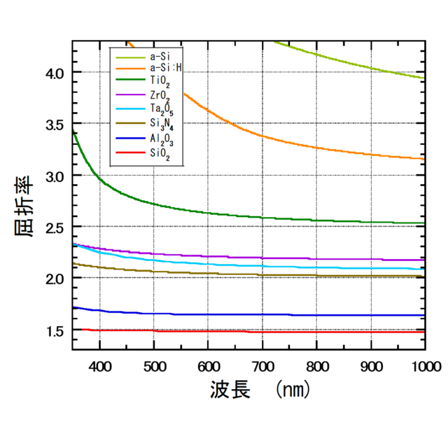
High refractive index control
Since there are direct reactions between a solid source and an oxygen or nitrogen ECR plasma flow, high-refractive index control is possible, with no generation of intermediate products as happens with CVD. In addition, films having any desired refractive index can be created simply by making oxygen and nitrogen flow simultaneously.
High-reactivity deposition
Rapid deposition is enabled by reactions between a solid source and a large-current ECR plasma of a gas such as oxygen or nitrogen.
Low-temperature, low-damage, surface cleaning effect
Deposition is by the ion-assist effect at a low energy but high current, making it possible to form high-quality, highly crystalline thin films at low temperatures and with low levels of damage, in comparison with conventional deposition methods. Cleaning of the substrate and grown surfaces can also be expected.
- 3″ tray automatic conveyor. Five trays can be set.
- High-throughput processing of deposition on five trays in sequence, with no fall in the plasma
- High-vacuum support by three-chamber system
- Two branch-coupler-type ECR plasma sources, suitable for mass-production
- Fully automatic conveying and multi-layer deposition, up to maximum of 22 layers
- New electrical system
Detailed display of error information
Larger operations screen
Recipe back-up function, etc - optional data logging system
Vdc plotter
New spectral system that enables measurement of film thickness and refractive index variance within the deposition chamber
Additional magnetron sputtering sources (maximum 2)
Additional gas lines (maximum 2)
| Item | Specifications |
|---|---|
| Achieved pressure | Processing chamber: Max. 3 x 10⁻⁵ Pa Load lock chamber: Max. 3 x 10⁻⁴ Pa |
| Vacuum exhaust system | Deposition chamber: turbo molecular pump, 1000 l/sec Load lock chamber: turbo molecular pump |
| Deposition chamber | |
| Deposition chamber | Microwave branch-coupler-type ECR ion sources: 2 |
| Substrate holder | Flat step rotation Substrate size: Max. 3” |
| Substrate heating | Maximum 400℃ |
| Substrate position | Distance from target to substrate: 170 mm |
| Load lock chamber | |
| Conveyor method | Automatic tray conveying, 5 trays processed together |
| Number of samples | Load lock chamber: 5 trays can be set |
| ECR sputtering source | |
| Quantity | 2 |
| Plasma source | Microwave branch-coupler-type ECR plasma source |
| Plasma chamber | Internal diameter 150 mm, water-cooled jacket structure |
| Cylindrical target | Cylindrical, internal diameter 100 mm x width 40 mm, backing tube, direct cooling system |
| Gas introduction lines | Mass-flow controller: 3 lines Gases: argon, oxygen, nitrogen |
| Operations | |
| Exhaust | Automatic |
| Substrate conveying | Automatic |
| Deposition | Automatic/manual (switchable) |
| Deposition control power sources | |
| For ECR ion source | Microwave power sources (2): 2.45 GHz, 1kW Coil power sources (2): DC 1.5 kW (2) |
| For ECR sputtering | Target power sources (2): RF 13.56 MHz, 1 kW |
| Installation conditions | |
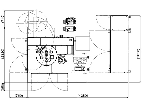
| Space | 3.5 x 3 m (including work space) |
| Electrical power | Three-phase, 200 V, 75 A, 30 A, one system for each |
| Coolant water | Flow rate: 20 V/min Water pressure: 3 to 4 kg/cm2 G |
| Weight | 2000kg |
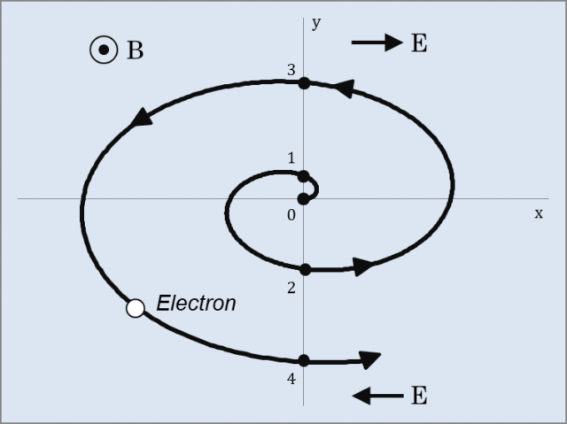
ECR Principle
High refractive index control
- No electrical power, low gas pressure (0.01-0.2 Pa), large-current ion bombardment effect at low energies (10-30 eV) to a high-density (5-10 mA/cm²) substrate surface
- Formation of precise, smooth, high-quality thin films, with low heating and low damage
Physical properties of ECR thin films
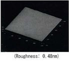
Flatness
Hardness
SiN films and carbon films have hardnesses similar to those of diamondStrictness
Superior optical characteristics
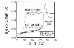
Impurity-free
High-purity target and gas used as ingredients to achieve high levels of purity with no reaction products (H, F, CI, etc.)High compoundability
Orientation of AIN films, MgO films, etc. Low-resistivity TiN films and α-Ta films.Coatability
Coatability of bumps is much higher than with general sputtering, by formation of inclined rotation film at low gas pressure and high ionization rate.High voltages
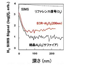
High-voltage insulation film similar to bulk. 10 MV/cm for SiO2 and Al2O3 films (similar to 1000°C thermal oxidation film).Low damage
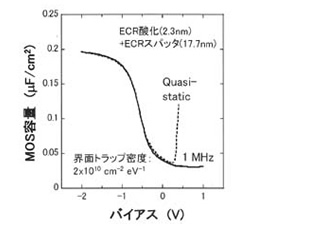
High permittivity
Formation of boundary oxide films inhibited by metal-mode depositionDrawing & Diagram

Contact Us
TEL 045-787-7203 / FAX 045-787-8472
Please feel free to contact us, you can reach us with phone or thru contact form here.
